The Harris “Gates” series AM transmitters were produced approximately 1990-2000 and most are still providing good service.
This is a later unit and it’s tripped a fault alarm at the studio after overnight storms. Let’s take a look!

Sure enough. This is perhaps the most common failure with these transmitters. Generally a shorted FET blows the protection fuse, tripping the fuse fault light. The transmitter continues to run at slightly reduced power. This one has a blown fuse in PA#3 (there are four power amplifier boards inside)
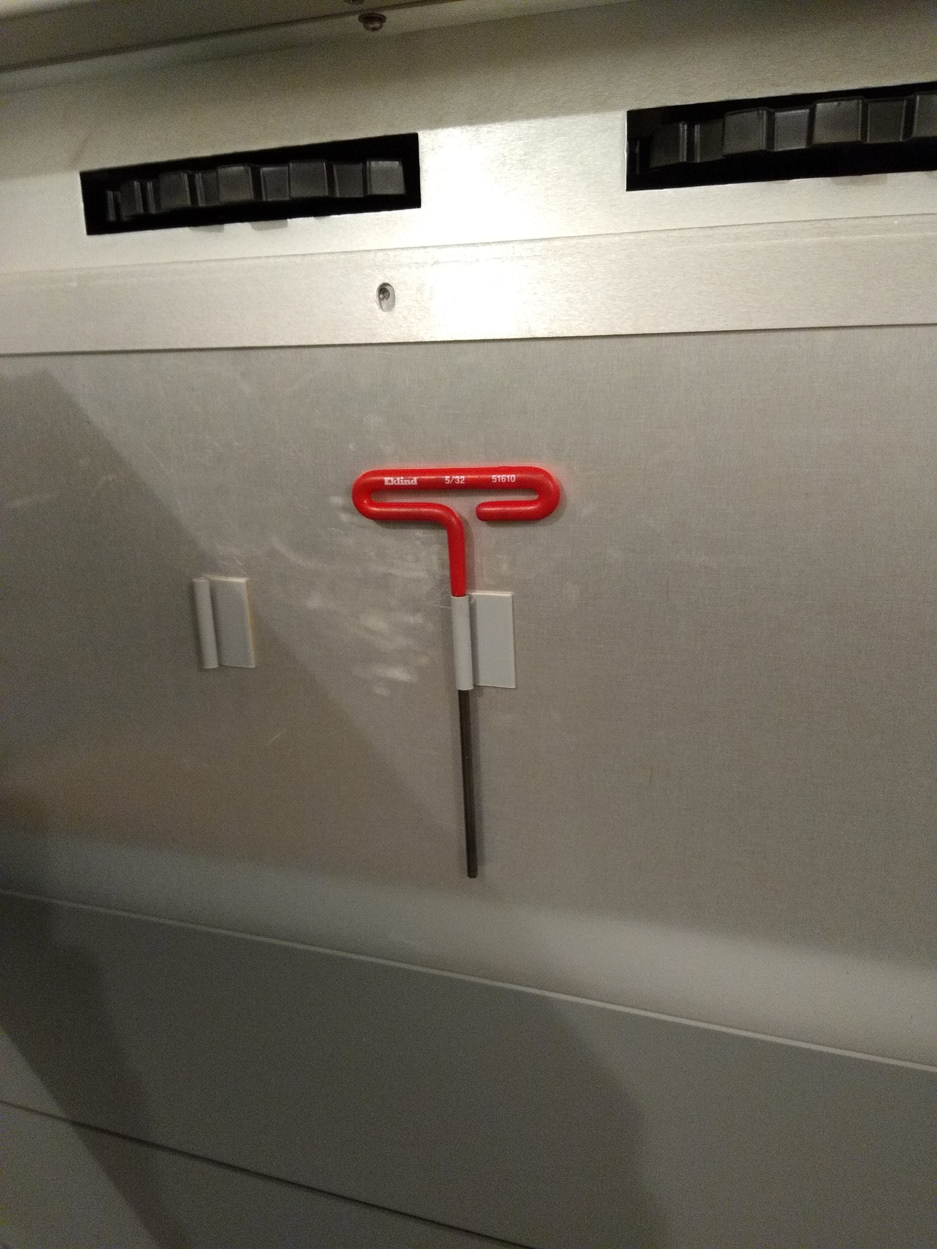
To access it we need to turn the transmitter Off, remove power to it and open the rear door. Harris provided a tool for that

Right behind the control panel door. Earlier versions used a plain phillips head fastener. These later units need a 5/32″ Allen.
First thing I do after removing the rear door is to give the power supply shorting bars a nudge with an insulated stick. They seem to take a “set” and don’t always close correctly when the rear panel is opened. While these transmitters do not use thousands of volts like their tube-type predecessors did, they can supply tremendous amounts of current. There is also a shorting stick provided to discharge capacitors. Always use it.

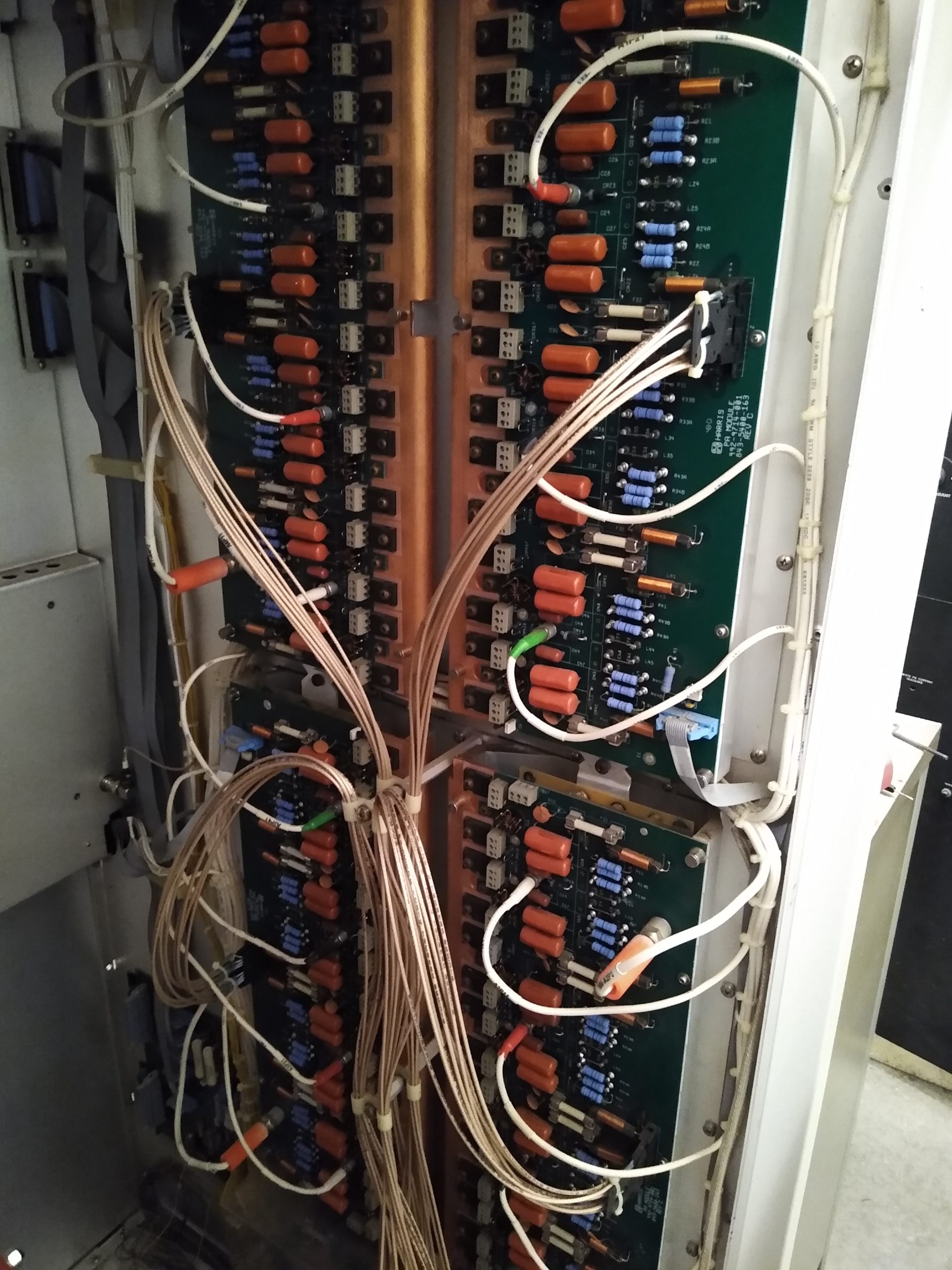
Here are the four power amplifier boards. There is one fuse for each pair of FET’s. The fuse protects the printed circuit board from a shorted FET as they can pull enough current to vaporize it. A test meter set to audible resistance check makes short work of finding the bad fuse.
The spaghetti looking cables are coaxial cables from the IPA, carrying drive power to each amplifier quad.

A closer look at the FET pair. Later Gates series used these socketed plastic case FET’s. Replacing them is as simple as loosening the three socket screws and removing the hold down screw. Earlier versions used metal “TO3” style FETs which required the entire board be removed so they could be unsoldered.

Here are the parts needed: IRF 350 FETs, 4A “instrumentation” fuses (very fast blow) and Heat sink pads for the FET’s. All available from Gates Air, the transmitter manufacturer as well as various third party suppliers.
It’s not technically necessary to replace the heat sink pad, but it’s good insurance and they’re cheap.

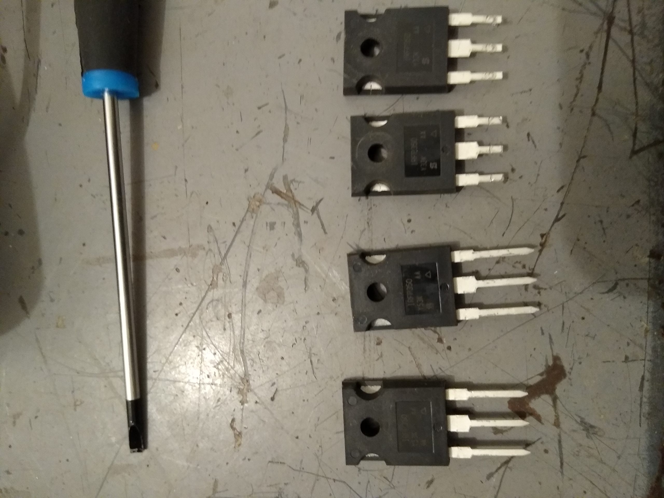
The new FET’s (bottom) do need to be trimmed to fit the sockets. Simply matching them up with those removed works fine.
Install the FETS and fuse, re-install the rear door, apply power and..

There we go! Fault cleared, transmitter back to full power. Now on to the next call…
